Bridgeport Series 1 Mill with EMC Control
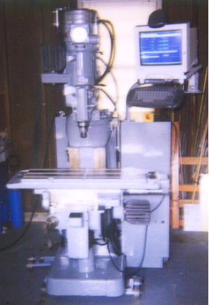
This is a Bridgeport Series 1 CNC mill that I cleaned, painted, and retrofitted with new electronics. In case you're wondering about the wheels, it's sitting on a pair of homemade machinery skates so that I can roll it around. The machine came to me through a dealer who got it from a plastics company here in Baltimore. It was very dirty and some of the original electronics were missing, having been salvaged to keep other machines running. I removed all the remaining electronics and and electrical enclosures prior to pressure washing the machine to remove the accumulated grime. All the machined surfaces were then masked (this took a whole day!) and the painted surfaces were wiped down with PPG's Ditz-o DX440 Wax & Grease Remover. This was followed by two coats of Rust-oleum #7786 Smoke Grey Gloss Enamel to which was added PPG DX73 Fisheye Eliminator and thinned to spraying consistency with laquer thinner. My friend Steve (who paints cars professionally) applied the paint, and told me what painting supplies to get. Although the paint dried to the touch overnight, it took about a week or so for the paint to reach its final hardness. I've accidently dropped tools on the top of the electrical cabinets and the paint hasn't chipped or even been marked, so I'm pleased with the results. Once the painting was done, I cleaned all the small miscellaneous parts with a rotary wire brush in the drill press, or with solvent, rags and Q-tips. I then reassembled the machine and did some work to the head which involved replacment of the drive belt and some worn out bearings in the variable speed drive. The pneumatic system was in pretty good shape, although I did install a new Wilkerson Filter/Regulator/Lubricator as the original unit was missing. The original operator's pendant was discarded and an angle bracket machined to bolt in its place which supports a parallel link style monitor arm with keyboard rack. On this sits a MAG DX15F SVGA monitor and a wireless keyboard from Casco Products International of Cedar Rapids, Iowa, USA with integral pointing device. The original e-stop button was mounted in a box screwed to the right side of the quill housing facing the operator, along with some other switches that were now unnecessary. This entire box (along with another similar one from the left side of the quill housing) was discarded and
replaced with a new e-stop pendant on the end of a length of SO cord (you can see this sitting on top of the side electrical enclosure just below the keyboard). I retained the original spindle motor, axis drive motors and axis limit switches, but all the wiring has been replaced.
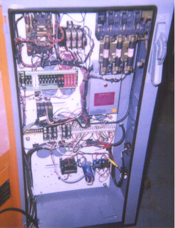
This is the rear electrical cabinet which contains the bulk of the electrical controls. At the upper left is the spindle motor contactor, and to its right is the spindle motor overload circuit breaker. At the upper right is the main power disconnect switch and fuse block. Immediately below the fuses is a Phase-o-matic static phase converter used to run the spindle
motor, which is the only three phase load in the entire machine. To the left of the phase converter is an Opto22 rack that allows the 5Vdc signals of one of the PC's parallel ports to interface with the higher voltage control circuits. The two white modules on the left side of the rack are input modules for e-stop and lube oil level sensors. Further right on the rack are two black ac output modules that drive the 110Vac coils of the spindle motor contactor. Three of the four red dc output modules drive the 24Vdc pneumatic valves that operate the spindle brake and the air motor that increases or decreases the spindle
speed. The fourth red dc output module is for e-stop output from the PC. Below the Opto22 rack is the e-stop contactor which removes ac power from the spindle motor, axis drives, and the coolant receptacles when the control is in e-stop. Below the e-stop relay and phase converter is a piece of DIN rail upon which are various fuse and terminal blocks used to interconnect the system wiring. At the bottom of the cabinet, from left to right are the transformer and blue filter capacitor for the 24Vdc power supply (the bridge rectifier is mounted between them, but it's rather small and hard to see in this picture). At the bottom right are two solid state relays
that switch the power to the mist and flood coolant receptacles on the right side of the enclosure (the yellow item is a fuse holder).
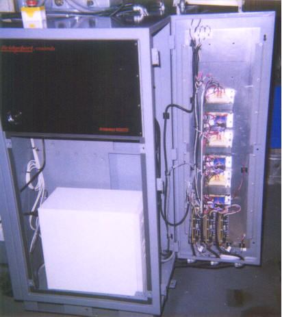
This view is of the side mounted electrical enclosure which used to be crammed full of the original DEC LSI-11 computer and associated power supplies, but now contains the PC which runs the EMC cnc control software under Red Hat Linux V5.2 with real time extensions. The PC is an Intel 350MHz Pentium 2 on an Intel Seattle 2 motherboard with 128MB of RAM, an ATI Mach64
video card, an Intel EtherExpress PRO/100+ network card, a Memorex CD-402E CDROM drive and a Teac 3-1/2" floppy drive. There are also two separate parallel port adapters plugged into the backplane that control the machine (the parallel port integral with the motherboard is not used). The hole in the enclosure through which you can see the PC is normally covered by a louvered panel containing a fiberglass air filter. Behind the smoked acrylic door is an empty 19" equipment rack that used to contain a paper tape reader and some toggle switches. In the top rear of the enclosure are a pair of fans that draw cooling air in through the louvered panel and filter and exhaust it through a hooded duct. All the gasketing that seals the doors has been replaced. Mounted on the inside of the rear door are three model 7205 power supplies and three model DR8010 motor drivers from Microkinetics. I've drilled mounting holes and prewired for a fourth axis in case someone wants to hook up a rotary table or indexer in the future.
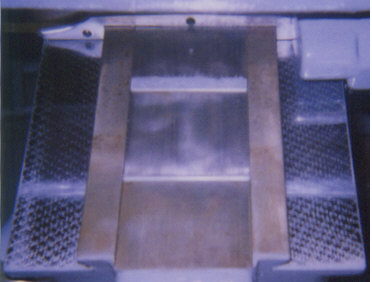
Here is a view of the top of the knee showing the chrome ways. As you can see its in good shape despite its age.
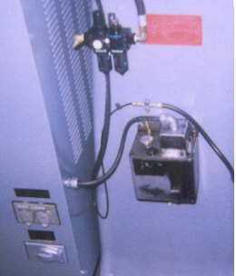
This is the left side of the machine showing the Wilkerson filter/regulator/lubricator (top), the Bijur automatic lube pump(below), and the electrical outlets for coolant pumps (below left). The Spraymist unit mounts directly below the lube pump (not mounted when this picture was taken).


